Stepped BCT · Oblique ledges
BCT(211)
BCT(211) exposes oblique ledges whose widths and inclinations depend on the tetragonal c/a ratio. It extends the low-index set into a compact stepped surface.
- Plane
- (211)
- Layer character
- Stepped · anisotropic
- ASE slab builder
surface
From bulk to facet
How BCT(211) is cut

(211)
Unequal basal indices and a finite c-axis index make the plane intersect all three conventional tetragonal axes at different distances.
- Bulk lattice
- Body-centred tetragonal
- Plane normal
- reciprocal vector G(211)
- What remains
- Oblique ledges
The plane is drawn through the centre so high-index cuts remain legible. Its orientation is what the indices specify, not its absolute position inside one cell.
Surface geometry
Read the surface from above
L1 is the highest atom-bearing plane, followed by L2 and L3. Support coordinates outside 0–1 are periodic images. The listed Δz describes the supporting atoms, not the marker height. In the interactive model, every numbered site is placed on the same schematic guide plane above the slab; no adsorption distance or energetic ordering is implied.
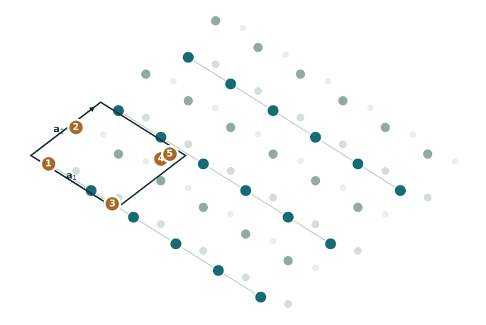
- ledge ontop1-fold
Above an atom on the highest ledge.
(u,v) = (0.1857, 0.0286)s = s₁ · support shell: mean Δz = +0.000 Å from L1Projection of the L1 atom at (0.1857, 0.0286).
Not named in ASE - lower-row ontop1-fold
Above an exposed atom in the next atom-bearing plane.
(u,v) = (0.054, 0.581)s = s₁ · support shell: mean Δz = -1.395 Å from L1Projection of the L2 atom at (0.054, 0.581).
Not named in ASE - ledge bridge2-fold
Between nearest atoms along the upper ledge.
(u,v) = (0.9357, 0.0286)s = (s₁ + s₂) / 2 · support shell: mean Δz = +0.000 Å from L1Periodic midpoint of L1 (-0.3143, 1.0286) and L1 (0.1857, 1.0286).
Not named in ASE - cross-ledge bridge2-fold
Between atoms on adjacent exposed height levels.
(u,v) = (0.8699, 0.8048)s = (s₁ + s₂) / 2 · support shell: mean Δz = -0.697 Å from L1Periodic midpoint of L1 (0.6857, 0.0286) and L2 (1.054, -0.419).
Not named in ASE - mixed-height pocket3-fold
A pocket supported by atoms from consecutive ledges.
(u,v) = (0.8873, 0.9143)s = (Σᵢ sᵢ) / 3 · support shell: mean Δz = -1.395 Å from L1Least-squares centroid of the 3-atom projected shell: L1 (0.6857, 0.0286), L2 (1.054, -0.419), L3 (0.9222, 0.1334).
Not named in ASE
Interactive model
Rotate the slab
Sites share a schematic display height · drag to rotate · hover for names
Below the top layer
Why the sites are different
Each atom-bearing plane contains two staggered sites, followed by a shifted pair in the next layer. Mixed-height sites span both the body-centred basis and the step sequence.
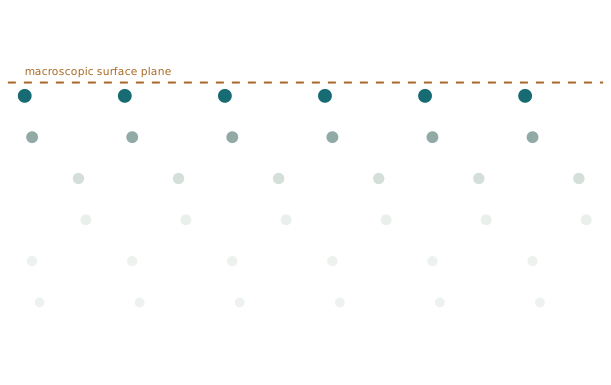
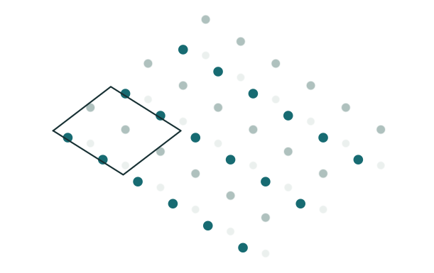
Cell
Geometry at a glance
The spacing is \(d_{211}^{-2}=5/a^2+1/c^2\). The even body-centred phase places corner and centre sites in the same plane family member.
A site name describes the ideal starting geometry. Relaxation can move an adsorbate away from it.
Practical model
Build it with ASE
The builder creates the slab. Sites marked ASE keyword can be passed directly as a named position; ASE source marks current but inconsistently documented support. Other sites require explicit Cartesian coordinates converted from the fractional construction above.
from ase import Atoms
from ase.build import surface

a, c = 3.25, 4.95
indium = Atoms("In2", scaled_positions=[(0, 0, 0), (.5, .5, .5)],
               cell=[(a, 0, 0), (0, a, 0), (0, 0, c)], pbc=True)
slab = surface(indium, (2, 1, 1), 10, vacuum=10)
Things that are easy to misread
- Reusing cubic BCC(211) dimensions without applying the tetragonal metric.
- Counting atoms in projection without separating the paired height levels.