Mixed-index BCT · Anisotropic rows
BCT(101)
BCT(101) mixes one basal reciprocal component with the c-axis component. It is not symmetry equivalent to (110) unless the tetragonal distortion disappears.
- Plane
- (101)
- Layer character
- Mixed basal–axial · corrugated
- ASE slab builder
surface
From bulk to facet
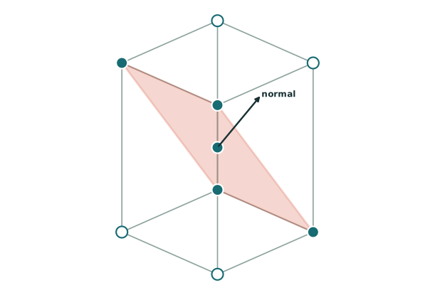
How BCT(101) is cut
(101)
The plane cuts one basal axis and the c axis while remaining parallel to the second basal direction, producing rows with a c/a-dependent inclination.
- Bulk lattice
- Body-centred tetragonal
- Plane normal
- reciprocal vector G(101)
- What remains
- Anisotropic rows
The plane is drawn through the centre so high-index cuts remain legible. Its orientation is what the indices specify, not its absolute position inside one cell.
Surface geometry
Read the surface from above
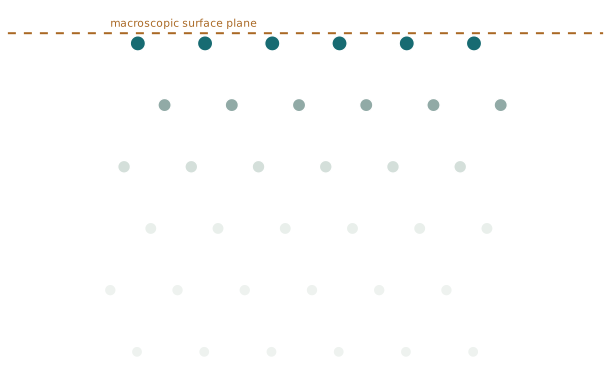
L1 is the highest atom-bearing plane, followed by L2 and L3. Support coordinates outside 0–1 are periodic images. The listed Δz describes the supporting atoms, not the marker height. In the interactive model, every numbered site is placed on the same schematic guide plane above the slab; no adsorption distance or energetic ordering is implied.

- outermost ontop1-fold
Above an atom in the highest exposed row.
(u,v) = (0.211, 1/2)s = s₁ · support shell: mean Δz = +0.000 Å from L1Projection of the L1 atom at (0.211, 1/2).
Not named in ASE - lower-row ontop1-fold
Above an exposed atom in the next atom-bearing plane.
(u,v) = (0.4098, 0)s = s₁ · support shell: mean Δz = -2.717 Å from L1Projection of the L2 atom at (0.4098, 0).
Not named in ASE - row bridge2-fold
Between periodic neighbours within the outermost row.
(u,v) = (0.211, 0)s = (s₁ + s₂) / 2 · support shell: mean Δz = +0.000 Å from L1Periodic midpoint of L1 (0.211, 1/2) and L1 (0.211, 3/2).
Not named in ASE - cross-row bridge2-fold
Between atoms in neighbouring projected rows.
(u,v) = (0.5604, 0)s = (s₁ + s₂) / 2 · support shell: mean Δz = -1.358 Å from L1Periodic midpoint of L1 (0.711, 0) and L2 (0.4098, 0).
Not named in ASE - mixed-height pocket3-fold
A three-atom opening supported by consecutive atom-bearing planes.
(u,v) = (0.5765, 1/6)s = (Σᵢ sᵢ) / 3 · support shell: mean Δz = -2.717 Å from L1Least-squares centroid of the 3-atom projected shell: L1 (0.711, 0), L2 (0.4098, 0), L3 (0.6086, 1/2).
Not named in ASE
Interactive model
Rotate the slab
Sites share a schematic display height · drag to rotate · hover for names
Below the top layer
Why the sites are different
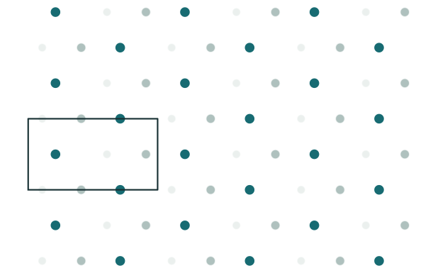
Two outermost rows share L1, while subsequent planes shift across the long mixed-index repeat. Lower-layer checks distinguish bridges from deeper pockets.
Cell
Geometry at a glance
The spacing is \(d_{101}^{-2}=1/a^2+1/c^2\). One in-plane repeat is the untouched basal translation; the other combines a and c.
A site name describes the ideal starting geometry. Relaxation can move an adsorbate away from it.
Practical model
Build it with ASE
The builder creates the slab. Sites marked ASE keyword can be passed directly as a named position; ASE source marks current but inconsistently documented support. Other sites require explicit Cartesian coordinates converted from the fractional construction above.
from ase import Atoms
from ase.build import surface

a, c = 3.25, 4.95
indium = Atoms("In2", scaled_positions=[(0, 0, 0), (.5, .5, .5)],
               cell=[(a, 0, 0), (0, a, 0), (0, 0, c)], pbc=True)
slab = surface(indium, (1, 0, 1), 8, vacuum=10)
Things that are easy to misread
- Treating (101) and (110) as symmetry-equivalent cubic permutations.
- Comparing slabs without reporting both a and c.